Yanmar parts catalogue / 26206-120452 BOLT, M12X 45 PLATED

26206-120452 BOLT, M12X 45 PLATED — YANMAR

Yanmar 26206-120452 BOLT, M12X 45 PLATED — position on the assembly diagram
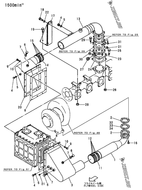
15
The part position is highlighted in red on the diagram
  • Part number: 26206-120452
  • Manufacturer: Yanmar
  • Name: BOLT, M12X 45 PLATED
  • Weight: 500 g
  • Length: 30 mm
  • Width: 100 mm
  • Height: 50 mm

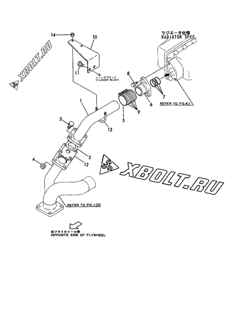
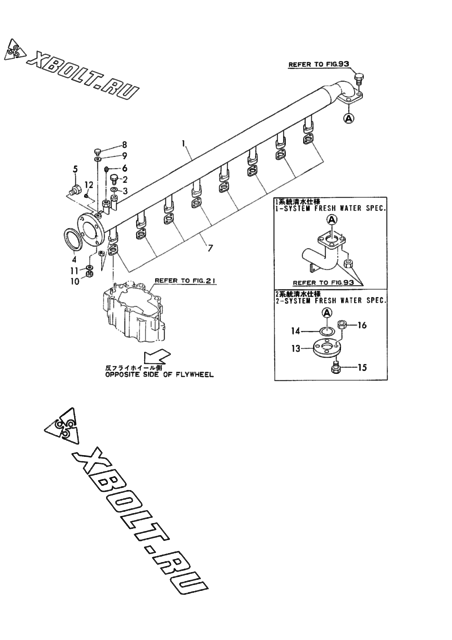
The diagram shows the assembly “Breather(control side)” of the Yanmar 6/8NHL engine.

Check sellers for 26206-120452 on pFind.pro

Where part 26206-120452 is used

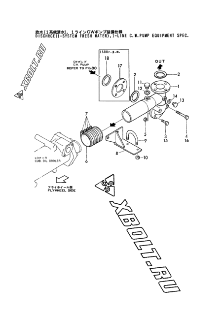
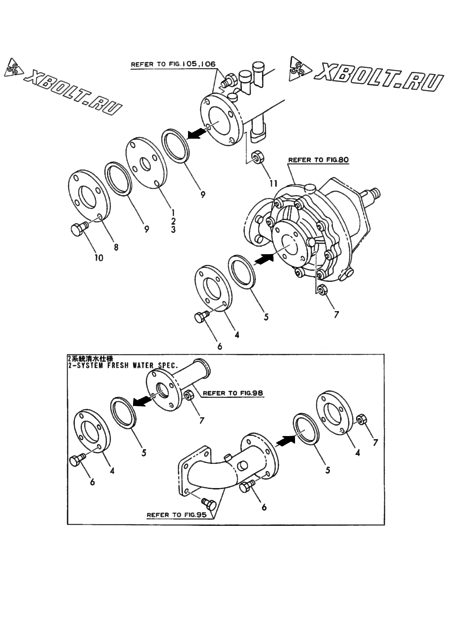
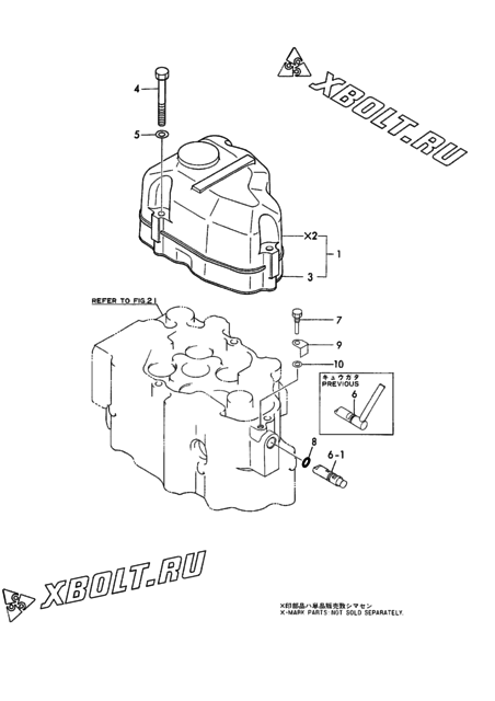
Yanmar part 26206-120452 is used in 21 engine models. Assemblies: c.w.pipe(vtr354)(t/c ofw.side), flywheel side cover & oil shield cover, c.w.pipe(vtr354)(t/c ofw.side)(30-deg.inclination spec) and 50 more.

Engine assemblyDiagram pos.QtyEngine modelsCatalogue notes
Fuel pipe(feed pump-notch wire st.)(w emer.inlet) 8 8
C.w.pipe(VTR354)(t/c ofw.side)(30-DEG.INCLINATION spec) 15 2
C.w.pipe(VTR354)(t/c ofw.side) 15 2
Flywheel side cover & oil shield cover 4-1 4
  • Interchangeability: new part number replaces the old one, not vice versa
Mist breather pipe(gear housing side)(t/c fw.side) 12 8
L.o.pipe(generator bearing,sea water valve) 16 16
L.o.pipe(mansei priming pump)(for notch strainer) 15 2
Optional part 29 8
Optional part 4 4
L.o.pipe(pcv.-cylinder)(8N330L-UV,sv,ev) 6 2
T/c washing device(2)(t/c fw.side) 20 1
C.w.pipe(air cooler out) 8 4
Fuel pipe(feed pump-metal screen st.)(w emer.inlet) 7 8
Lub.oil press.regulating valve 15 2
Cooling water concentric pipe 15 4
Bonnet & decompression 4 18
Bonnet & decompression 4 24
Option(caster,flange) 13 4
Option(caster,flange) 17 8
Fuel pressure gauge pipe(f.o.chamber) 54 1
Fuel pressure gauge pipe(f.o.chamber) 13 1
Cooling water pipe(1-line) 5 4
Cooling water pipe(2-line) 31 4
Fuel pressure gauge pipe(f.o.chamber) 18 2
L.o.pipe(mansei priming pump)(for ihi strainer) 16 2
L.o.pipe(TPL65)(t/c ofw.side) 16 3
L.o.pipe(pcv.-cylinder)(8N330L-GV)(t/c ofw.side) 6 2
L.o.pipe(pcv.-cylinder)(8N330L-GV)(t/c fw.side) 6 2
Cooling water pipe(1-line) 26 4
C.w.pipe(air cooler) 7 6
C.w.pipe(c.w.pump-air cooler) 3 4
Air cleaner&silencer(YAG20,25S 23 4
L.o.pipe(TPL65)(t/c fw.side) 16 6
Flywheel side cover & oil shield cover 4-1 4
  • Interchangeability: new part number replaces the old one, not vice versa
  • Applies from: Engine No 00127
Lub.oil pipe(turbocharger) 27 2
Breather 16 3
Lub.oil overflow pipe(strainer) 8 3
Lub.oil pipe(pump-cooler) 2 4
Lub.oil pipe(wing pump) 12 5
Cooling water pipe(pump outlet) 14 4
Tool 73 1
  • NOT ILLUSTRATED.
Fuel pipe(strainer-main pipe-regurlating valve) 21 4
Air cooler casing 14 6
C.w.outlet orifice & eye flange 6 4
  • FRESH WATER 1-SYSTEM SPEC.Q'TY=4 FRESH WATER 2-SYSTEM SPEC.Q'TY=12
Tension pully(radiator) 12 2
Tension pully(radiator) 12-1 1
  • Interchangeability: quantity in the assembly changed
  • Applies from: date 1993.12
C.w.pipe(c.w.pump inlet,thermostat) 11 4
C.w.pipe(c.w.pump inlet,thermostat) 3 4
C.w.pipe(c.w.pump-cylinder) 3 2
C.w.pipe (c.w.pump-l.o.cooler) 3 2
Mist breather pipe ofw.side & flange(common eng.) 19 8
  • NOT ILLUSTRATED
Mist breather pipe ofw.side & flange(common eng.) 14 4
  • NOT ILLUSTRATED
C.w.pipe(air cooler) 6 4
Lub.oil pipe(press.regulat.v.) 3 1
Breather 15 4
Lub.oil suction pipe 6 3
Air duct 26 2
Breather(control side) 15 4
Suc.press.gauge pipe(RU120A-2) 25 4
Suc.press.gauge pipe(RU110) 25 4
Lo.pipe(oil pan/strainer-cmb,priming pump) 23 4
  • NOT ILLUSTRATED.
Lo.pipe(press.regulat.valve-cylinder) 5 2
Fo.chamber & fo.pipe(return pipe-pcv.-feed pump) 73 2
  • NOT ILLUSTRATED.
C.w.pipe (c.w.pump-air cooler) 3 4
C.w.pipe(c.w.pump-air cooler) 3 2
Lub.oil pipe(l.o.sump-l.o.cooler) 19 4
  • NOT ILLUSTRATED.

Other parts of the “Breather(control side)” assembly, Yanmar 6/8NHL

  Open the assembly diagram

Assemblies with this part