Yanmar parts catalogue / 26706-080002 NUT, M8

26706-080002 NUT, M8 — YANMAR

Yanmar 26706-080002 NUT, M8 — position on the assembly diagram
17
The part position is highlighted in red on the diagram
  • Part number: 26706-080002
  • Manufacturer: Yanmar
  • Name: NUT, M8
  • Weight: 5 g
  • Length: 10 mm
  • Width: 10 mm
  • Height: 5 mm

The diagram shows the assembly “Flange & coupling” of the Yanmar 6T95L-GB engine.

Check sellers for 26706-080002 on pFind.pro

Where part 26706-080002 is used

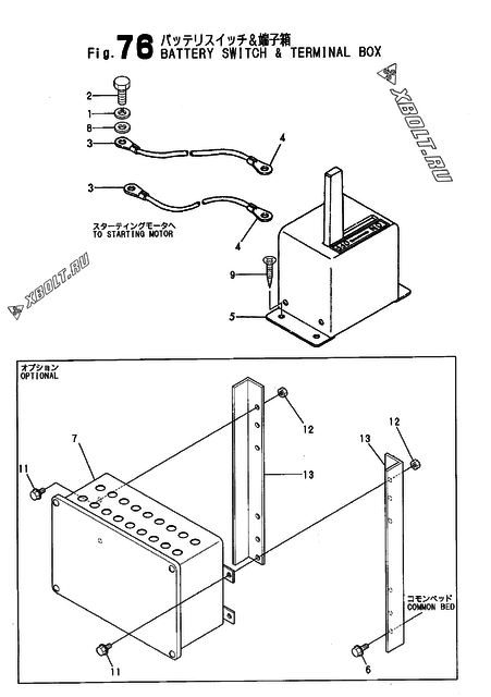
Yanmar part 26706-080002 is used in 79 engine models. Assemblies: bonnet, battery switch & terminal box, tachometer driving device and 121 more.

Engine assemblyDiagram pos.QtyEngine modelsCatalogue notes
Battery switch & terminal box 12 4
Bonnet 96 4
Tachometer driving device 10 2
Fuel pipe(feed pump-notch wire st.)(w emer.inlet) 18 2
F.i.pipe overflow pipe & overflow detecting device 12 2
Booster assy 9 4
Fuel pipe(feed pump-metal screen st.)(w/o emer.inlet) 9 2
Fuel overflow tank(mdo) 4 2
Fuel pipe(feed pump-notch wire st.)(w/o emer.inlet) 10 4
NO.2 fuel strainer(notch wire type)(MDO/7000SEC.OIL) 18 1
Fuel inlet pipe(mdo) 12 2
C.w.pipe(VTR354)(t/c ofw.side)(30-DEG.INCLINATION spec) 14 6
C.w.pipe(VTR354)(t/c ofw.side) 14 6
C.w.pipe(VTR354)(t/c ofw.side) 35 4
Blower washing device(t/c fw.side) 14 2
T/c washing device(2)(t/c ofw.side) 23 4
C.w.pipe(VTR354)(t/c fw.side) 32 4
C.w.pipe(VTR354)(t/c fw.side) 12 2
T/c washing device(2)(t/c fw.side) 31 1
Blower washing device(t/c ofw.side) 15 2
Radiator support 32 2
Flange & coupling 17 2
Bonnet 24 2
Bonnet 97 4
Cylinder side cover(relief valve) 28 44
  • Interchangeability: part is discontinued
Cylinder side cover(relief valve) 38 44
  • Interchangeability: additional part
  • LR,NV,AB,BV,HK,CR,KR,GL,NK,RINA
T/c washing device(2)(t/c fw.side) 34 1
Motor turning device(aux.engine)(optional) 11 2
L.o.pipe(lub.oil sump-cmb.)(dry sump spec) 7 6
L.o.return pipe(notch strainer-cmb) 13 2
Foot plate & step(exhaust pipe side)(aux.engine) 16 14
Mist breather pipe(gear housing side)(t/c fw.side) 20 4
Foot plate & step(control side)(aux.engine) 22 20
L.o.pipe(fuel pump pinion oiling)(7000 sec.oil spec) 23 1
Instrument board bracket(aux.engine) 4 8
L.o.pipe(generator bearing,sea water valve) 12 4
Solenoid 11 4
Crankshaft & flywheel 31 4
  • NOT ILLUSTRATED.
Air chamber 14 2
Bonnet 94 4
L.o.wing pipe(for sanshin priming pump) 17 2
A/c by-pass pipe(t/c fw.side) 33 2
Breather(optional) 24 2
  • NOT ILLUSTRATED.
Pressure lead pipe 14 3
  • Interchangeability: additional part
  • Applies from: date 1989.12
Pressure lead pipe 14 3
Air duct b(a/c heater YPC190-H75-CYL.)(t/c fw.side) 31 5
T/c washing device(2)(t/c fw.side) 9 2
Air cyl. & link device(for a/c heater)(t/c ofw.side) 6 4
Air duct b(a/c heater YPC190-H75-CYL.)(t/c ofw.side) 26 5
Air duct b(a/c heater YPC190-H75-CYL.)(t/c fw.side) 25 5
Fuel pipe(feed pump-metal screen st.)(w emer.inlet) 15 2
Bonnet 79 6
Lub.oil pipe(f.i.pump oilling) 11 2
Radiator, sub-tank & fan 25 4
Instrument board bracket(t/c ofw.side)(main engine) 4 8
Instrument board bracket(t/c fw.side)(main engine) 4 8
Laminate coupling 14 2
Actuator(PLUS4) 11 5
Foot plate(control side)(main engine) 20 20
Speed control device(hyd.oil governor) 13 2
Tool(1) 55 2
Air pipe(start control) 20 1
Air cyl. & link device(for a/c heater)(t/c fw.side) 6 4
Suc.press.gauge pipe(RU120A-2) 4 3
C.w.pipe(air cooler out) 13 2
C.w.pipe(c.w.pump-air cooler) 13 2
Lub.oil pipe(turbocharger) 5 2
Lub.oil pipe(turbocharger) 25 2
Electric part 7 4
Lub.oil pipe(turbocharger) 26 2
Actuator(PLUS4) 13 7
Lub. oil pipe(TF15) 12 3
Lub. oil pipe(TF15) 24 2
L.o.pipe(TPL65)(t/c fw.side) 24 4
Cylinder side cover(relief valve) 38 44
  • Interchangeability: additional part
  • Applies from: Engine No 00171
  • LR,NV,AB,BV,HK,CR,KR,GL,NK,RINA
Cylinder side cover(relief valve) 28 44
  • Interchangeability: part is discontinued
  • Applies from: Engine No 00171
L.o.pipe(TPL65)(t/c fw.side) 10 2
L.o.pipe(TPL65)(t/c ofw.side) 10 6
Difference pressure indicator(for ihi strainer) 4 2
C.w.pipe(lo/c-a/c)(t/c fw.side)(for b&k strainer) 33 2
Motor driving governor 42 4
Lub.oil pipe(priming pump/emergency) 8 2
Wiring 30 2
Wiring 54 2
Wiring 43 5
Starter switch 3 2
Air pipe(lack limit & stop) 33 2
Lub.oil gauge pipe 6 2
Speed contlor device 7 2
Governor driving device(psg) 4 4
Lub.oil pipe(turbocharger) 21 1
Cw.pipe(turbo.inlet/outlet),turbo.fw.side 14 4
Cw.pipe(turbo.inlet/outlet),turbo.ofw.side 14 4
NO.2 fo.strainer 15 1
  • NOT ILLUSTRATED.
Cw.pipe(turbo.inlet/outlet),turbo.fw.side 50 4
Indicator,difference pressure(ihi-moatti GM250A) 4 2
  • NOT ILLUSTRATED
Motor turning device 20 2
  • NOT ILLUSTRATED.
Blower washing device 25 2
F.i.pump chamber cover 13 1
Link cace(for s.g.governor) 53 4
L.o.priming pipe(w/common bed spec.) 25 4
Lub. oil priming pump 9 4
Fuel feed pump 51 2
Damper 27 1
Breather(control side) 22 2
Lub. oil cooler(non-priming) 29 2
  • W/THERMO SWITCH 2 SPEC. : OPTION. NOT ILLUSTRATED.
Lub. oil cooler(w/priming) 29 2
  • W/THERMO SWITCH 2 SPEC. : OPTION. NOT ILLUSTRATED.
Psg governor,driving device 39 4
Fuel cut(solenoid) 25 8
Radiator support 16 2
Fuel line(fuel pump-strainer) 28 3
Gas line 19 2
Starter switch & battely switch 32 4
Load indicator 7 1
Start limiter 15 1
Connector(psg governor) 12 2
Fo.inlet pipe(fo.feed pump) 12 2
Fo.pipe(feed pump-strainer) 13 4
Lub.oil pipe(turbocharger) 25 4
Ignition system 13 12
Ignition system 8 8
Suction pipe(mixer:TD10L) 4 4
Suc.press.gauge pipe(TD10L) 24 3
Lub.oil priming pipe 22 4
Lub.oil suction pipe 9 1
Breather 23 2
Exhaust manifold 26 4
Support(hyd.oil governor) 8 2
Fuel injection pipe 26 24
Fuel injection pipe(w/covering pipe) 26 13
Cooling water pipe(2-line) 47 4
Cooling water pipe(1-line) 14 4
Air duct 7 3
Lub.oil priming motor pump 7 4
Lub.oil pipe(turbocharger) 27 4
Air strainer(RU120A-2) 5 6
Starting air main pipe 15 2
Mtg.bracket,gauge panel 4 8
Air pipe(distrib.valve-startiing valve) 10 1
Booster assy. 9 4
Fo.overflow sump & float switch 17 2
Fo.pipe(feed pump-strainer) 13 2
Fo.overflow pipe & main pipe,fo.injection pipe overflow 40 2
Turbocharger(RU120A-1,RU140) 8 2
Air duct(RU140) 6 3
C.w.pipe(l.o.cooler-air cooler) 10 4
Air strainer(RU110) 5 6
C.w.pipe(air cooler out) 12 2
C.w.pipe (c.w.pump-air cooler) 13 2
Lub. oil pipe(RU140) 24 1
  • PARTS SHOW IN REMARK (1) ARE NOT ILLUSTRATED
Lub. oil pipe(RU120A) 7 2
  • PARTS SHOW IN REMARK (1) ARE NOT ILLUSTRATED
Hyd.oil governor driving device 17 4

Other parts of the “Flange & coupling” assembly, Yanmar 6T95L-GB

Open the assembly diagram