Yanmar parts catalogue / 26206-120252 BOLT, M12X 25 PLATED

26206-120252 BOLT, M12X 25 PLATED — YANMAR

Yanmar 26206-120252 BOLT, M12X 25 PLATED — position on the assembly diagram
6
The part position is highlighted in red on the diagram
  • Part number: 26206-120252
  • Manufacturer: Yanmar
  • Name: BOLT, M12X 25 PLATED
  • Weight: 36 g
  • Length: 100 mm
  • Width: 60 mm
  • Height: 30 mm

The diagram shows the assembly “Blind cover(c.w.pump seat,l.o.main gallery)” of the Yanmar 6/8NHL engine.

Check sellers for 26206-120252 on pFind.pro

Where part 26206-120252 is used

Yanmar part 26206-120252 is used in 34 engine models. Assemblies: generator, engine tool, no.2 fuel strainer(metal screen type)(mdo) and 117 more.

Engine assemblyDiagram pos.QtyEngine modelsCatalogue notes
NO.2 fuel strainer(metal screen type)(mdo) 20 6
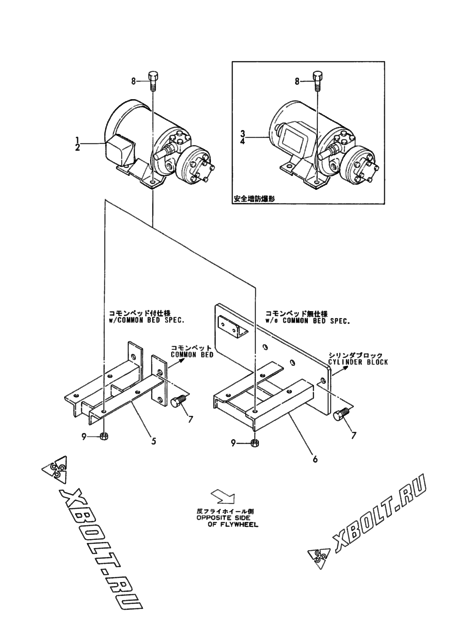
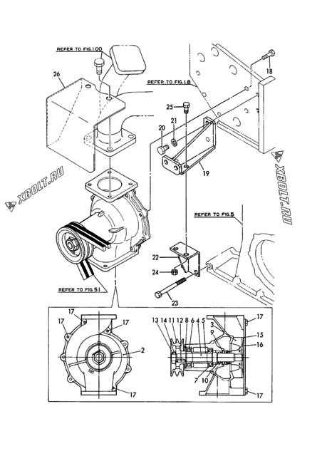
Fuel feed pump & driving device(cclkw.) 41 4
Fuel feed pump & driving device(clkw.) 41 4
NO.2 fuel strainer(notch wire type)(MDO/7000SEC.OIL) 13 6
Gear housing 29 8
Fuel pipe(feed pump-notch wire st.)(w/o emer.inlet) 3 2
Fuel pipe(feed pump-metal screen st.)(w/o emer.inlet) 5 2
C.w.collecting pipe(t/c ofw.side)(from E00137) 22 14
C.w.collecting pipe(t/c ofw.side)(up to E00136) 22 18
Exh.manifold cover(t/c fw.side) 12 42
Exh.manifold cover(t/c fw.side) 19 116
Oil shield cover(ofw.side) 18-1 4
Exh.manifold cover(t/c ofw.side) 12 44
Idle gear(camshaft driving) 20 5
C.w.collecting pipe(t/c fw.side)(from E00137) 22 14
C.w.collecting pipe(t/c fw.side)(up to E00136) 22 18
Fuel pipe(feed pump-notch wire st.)(w emer.inlet) 11 2
Fuel inlet pipe(hfo) 15 4
Fuel pipe(metal screen strainer-main pipe) 16 2
Fuel overflow tank(mdo) 13 2
Fuel overflow pipe(f.i.valve,f.i.pump) 20 16
Manual control air check valve 12 4
Auto.control air check valve & check valve 25 4
Engine tool 90 1
Bracket(auto.control air check valve)& bend 2 4
Fuel overflow pipe(f.i.valve return) 25 2
Booster assy 7 5
Fuel pipe(notch wire strainer-main pipe) 4 2
Fuel pipe(notch wire strainer-main pipe) 31 2
Fuel pipe(notch wire strainer-main pipe) 7 4
Fuel main pipe & accumulator 13 72
Fuel overflow pipe(f.i.valve return) 11 8
Fuel main pipe & accumulator 34 2
Exh.manifold cover(t/c ofw.side) 20-1 71
  • Interchangeability: quantity in the assembly changed
Exh.manifold cover(t/c fw.side) 19-1 72
  • Interchangeability: quantity in the assembly changed
Generator 21 2
Air duct b(a/c YPC190-CYLINDER)(t/c fw.side) 11 8
Blower washing device(t/c fw.side) 11 2
  • Not illustrated
Air duct b(a/c YPC190-CYLINDER)(t/c ofw.side) 10 64
Air duct b(a/c YPC190-CYLINDER)(t/c ofw.side) 12 8
Air duct b(a/c YPC190-CYLINDER)(t/c fw.side) 9 64
C.w.pipe(VTR354)(t/c fw.side) 10 2
Exh.manifold cover(t/c ofw.side) 20 122
Idle gear(lub.oil pump driving) 24 5
Motor turning device(aux.engine)(optional) 30 4
Fuel strainer(NO.1) 29 4
Fuel strainer(NO.1) 19 4
Fuel overflow sump(MDO/7000SEC.OIL) 23 2
Mist breather pipe(gear housing side)(t/c fw.side) 11 4
Air duct b(a/c heater YPC190-H75-CYL.)(t/c fw.side) 35 76
Air duct b(a/c heater YPC190-H75-CYL.)(t/c fw.side) 34 76
L.o.pipe(pcv.-cylinder)(8N330L-UV,sv,ev) 10 3
Air duct b(a/c heater YPC190-H75-CYL.)(t/c ofw.side) 35 76
Air cyl. & link device(for a/c heater)(t/c fw.side) 3 2
Support(fw.housing-lub.oil.sump) 3 9
Air cyl. & link device(for a/c heater)(t/c fw.side) 35 4
L.o.pipe(by-pass strainer) 11 1
Fuel sediment tank(100L) 22 4
Lub.oil pump 38 2
Mist breather pipe(flywheel side)(t/c ofw.side) 8 2
Fuel pipe(feed pump-metal screen st.)(w emer.inlet) 11 4
Fuel strainer(N0.1) 5 4
Idle gear(lub.oil pump driving) 11 5
L.o.pipe(by-pass strainer) 27 1
Fuel overflow sump(MDO/7000SEC.OIL) 12 4
Mist breather pipe(flywheel side)(t/c fw.side) 9 2
Generator 16 1
  • Part superseded, not shown on the diagram
  • Interchangeability: part is discontinued
  • Applies from: date 2003.10
Instrument board bracket(t/c fw.side)(main engine) 9 2
Fuel press.gauge pipe(3500/7000SEC.OIL)(main engine) 16 2
  • Interchangeability: part is discontinued
Fuel overflow tank(mdo) 24 2
Generator 3 4
Generator 17 2
Fuel sediment tank(100L) 5 4
C.w.pipe(exh.manifold out) 3 4
Air chamber cover & cam chamber cover 7 4
C.w.pipe(c.w.pump-l.o.cooler) 4 4
Fo.main pipe & accumulator 17 54
Fo.overflow pipe & main pipe,fo.injection pipe overflow 12 6
Fo.overflow pipe & main pipe,fo.injection pipe overflow 29 2
Fo.main pipe & accumulator 42 2
Exh.manifold(t/c fw.side) 45 2
Exh.manifold cover(t/c fw.side) 20 131
Exh.manifold(t/c ofw.side) 43 2
Booster assy. 7 5
Fo.pipe(strainer-main pipe) 25 2
  • NOT ILLUSTRATED.
Air check valve(for auto.control)& mtg. bracket,bend,flange 34 4
Cooling water pump (w/radiator spec.) 20 2
Thermostat 7 6
C.w.pipe(radiator-c.w.pump) 2 4
Generator ternator 3 3
Air pipe(distrib.valve-startiing valve) 7 1
Lub. oil priming pump 7 4
Exh.manifold cover(t/c fw.side) 20-1 88
  • Interchangeability: quantity in the assembly changed
Air check valve(for auto.control)& mtg. bracket,bend,flange 23 4
Engine tool 83 1
Air check valve(for manual control),flange 12 4
Exh.manifold cover(t/c ofw.side) 20-1 85
  • Interchangeability: quantity in the assembly changed
C.w.pipe(lo.cooler-cyl.block) 17 4
Air cooler 26 16
Throttle & indicator 15 4
Lub. oil pipe(TF15) 30 2
Fo.pipe(strainer-main pipe) 28 4
  • NOT ILLUSTRATED.
Fo.pipe(strainer-main pipe) 52 2
  • NOT ILLUSTRATED.
Fo.pipe(feed pump-strainer) 6 2
Blind cover(c.w.pump seat,l.o.main gallery) 6 3
Fo.pipe(strainer-main pipe) 21 2
Exhaust bend 13 1
Exhaust bend 15 2
  • Interchangeability: additional part
  • Applies from: date 1993.08
Air duct b(a/c YPC212-CYLINDER)(t/c ofw.side) 16 8
Air duct b(a/c YPC212-CYLINDER)(t/c fw.side) 14 64
Air duct b(a/c YPC212-CYLINDER)(t/c fw.side) 16 8
Exh.manifold cover(t/c ofw.side) 20 119
Air duct b(a/c YPC212-CYLINDER)(t/c ofw.side) 14 64
L.o.pipe(pcv.-cylinder)(8N330L-GV)(t/c fw.side) 10 3
Air duct(TF15) 15 2
Suction manifold 13 6
L.o.pipe(pcv.-cylinder)(8N330L-GV)(t/c ofw.side) 10 3
Suction manifold 12 8
Suc.press.gauge pipe(RU110) 19 2
Fuel injection pump driving device 20 4
Fuel strainer 45 3
Idle gear(camshaft driving),clkw. 13 5
Air duct(a/b),turbo.fw.side 23 60
Gear housing & flywheel housing 26 2
Exh.manifold & connect.pipe cover(t.ofw.side) 17 4
Mist breather pipe ofw.side & flange(common eng.) 10 4
Motor turning device 46 4
  • NOT ILLUSTRATED.
Exh.manifold & connect.pipe,cover(t.fw.side) 17 4
Air duct(a/b),turbo.ofw.side 18 60
Idle gear(lo.pump driving),clkw. 7 5
Cw.collect.pipe(parkerizing) 30 12
Cw.pipe(turbo.inlet/outlet),turbo.fw.side 12 2
Cw.pipe(turbo.inlet/outlet),turbo.ofw.side 12 2
NO.2 fo.strainer 10 6
  • NOT ILLUSTRATED.
Cw.pipe(cyl.inlet & pump-cyl.),2 line 15 6
  • NOT ILLUSTRATED.
Fuel pressure gauge pipe(f.o.chamber) 16 2
Lo.strainer(fo.injection pump plunger oiling) 7 2
Lo.pipe(press.regulat.valve-cylinder) 9 3
Lo.pipe(oil pan/strainer-cmb,priming pump) 28 4
  • NOT ILLUSTRATED.
Mist breather pipe,fw.side(emergency eng.) 11 2
Gear case & cover,oil shield cover,blank.cover 29 8
Exaust manifold 19 4
Idle gear 11 2
Lub.oil pipe(pump-cooler) 9 3
Lub.oil priming pipe 4 2
Flywheel cover 4 2
Cylinder side cover 24 12
Fo.feed pump & driving device 47 4
Suc.press.gauge pipe(RU120A-2) 19 2
Cylinder side cover 27 8
Fuel strainer 32 4
Fuel main pipe 21 14
Speed contlor device 3 4
Air pipe(air starter in) 3 2
Exhaust bend(TD10L) 5 6
Suction manifold 11 4
NO.2 fo.strainer 4 6
Fuel pipe(feed pump) 10 4
Fuel pipe(strainer-main pipe-regurlating valve) 12 2
Fuel pipe(strainer-main pipe-regurlating valve) 25 4
C.w.pipe(air cooler outlet) 8 2

Other parts of the “Blind cover(c.w.pump seat,l.o.main gallery)” assembly, Yanmar 6/8NHL

Open the assembly diagram