Yanmar parts catalogue / 26711-160002 NUT, M16

26711-160002 NUT, M16 — YANMAR

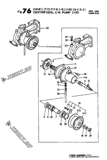
Yanmar 26711-160002 NUT, M16 — position on the assembly diagram
The part is shown on the diagram
  • Part number: 26711-160002
  • Manufacturer: Yanmar
  • Name: NUT, M16

The diagram shows the assembly “Air tank (optional)” of the Yanmar 6KHL-ST engine.

Check sellers for 26711-160002 on pFind.pro

Where part 26711-160002 is used

Yanmar part 26711-160002 is used in 32 engine models. Assemblies: cylinder block, engine tool, centrifugal c.w.pump(xr) and 60 more.

Engine assemblyDiagram pos.QtyEngine modelsCatalogue notes
Centrifugal c.w.pump(xr) 29 1
Fuel press.regulating valve(hfo) 24 4
Engine tool 88 1
Fuel press.regulating valve(mdo) 24 4
Air pipe(manual cont.air check v.-cont.v.) 19 8
Fuel inlet pipe(hfo) 23 4
Air starting control unit 3 8
Air duct b(a/c YPC190-CYLINDER)(t/c ofw.side) 34 4
Air duct b(a/c YPC190-CYLINDER)(t/c fw.side) 29 4
Centrifugal c.w.pump(xl) 29 1
Mist breather pipe(gear housing side)(t/c fw.side) 15 8
NO.1 lub.oil strainer(aux.engine) 30 16
NO.1 lub.oil strainer(aux.engine) 26 16
Motor turning device(aux.engine) 3 4
Mist breather pipe(gear housing side)(t/c fw.side) 26 8
Lub.oil cooler(aux.engine) 62 16
Lub.oil thermostat 7 16
L.o.pipe(cylinder in) 14 8
NO.2 lub.oil strainer 6 16
L.o.return pipe(notch strainer-cmb) 3 4
Fuel pipe(main pipe outlet)(t/c fw.side) 10 4
Air pipe(auto cont.air check v.-cont.v.)(aux.engine) 22 8
Fuel pipe(main pipe outlet)(t/c ofw.side) 10 4
L.o.pipe(lub.oil pump in) 8 8
L.o.pipe(cooler-pcv.) 12 8
Cylinder block 26 2
NO.2 l.o.strainer(notch wire type) 7 6
Cylinder block 13 5
L.o.pipe(lub.oil pump in) 13 8
Cylinder block 20 2
Air duct b(a/c heater YPC190-H75-CYL.)(t/c fw.side) 65 4
Air duct b(a/c heater YPC190-H75-CYL.)(t/c ofw.side) 58 4
Air duct b(a/c heater YPC190-H75-CYL.)(t/c fw.side) 56 4
Lub.oil cooler in/outlet pipe & thermostat 15 16
Lub.oil cooler(main engine) 46 16
Fuel sediment tank(100L) 42 4
Air pipe(auto cont.air check v.-cont.v.)(main engine) 16 8
C.w.strainer(single)(150A) 10 16
NO.1 lub.oil strainer(main engine) 29 16
L.o.press.regulating valve 20 8
Mist breather pipe(gear housing side)(t/c ofw.side) 14 8
Air tank (optional) 3 8
Air tank & air control panel 3 8
Lub.oil priming pipe 10 4
Cylinder block 15 5
Mist breather pipe(flywheel side)(t/c fw.side) 16 4
Mist breather pipe(flywheel side)(t/c ofw.side) 14 4
Fuel pipe(engine out) 9 4
Cylinder block 20 4
Exhaust flange.expansion joint 7 8
Fuel pipe(feed pump in) 9 4
Air starter(optional) 36 8
Cylinder block 15 3
Air duct b(a/c YPC212-CYLINDER)(t/c fw.side) 34 4
C.w.pipe(lo.cooler-cyl.block) 22 8
Tool 13A 4
  • Part superseded, not shown on the diagram
Difference pressure indicator(for ihi strainer) 8 2
Lub.oil cooler(aux.engine) 61 16
C.w.pipe(c.w.pump inlet,thermostat) 9 8
Air duct b(a/c YPC212-CYLINDER)(t/c ofw.side) 34 4
C.w.outlet orifice & eye flange 11 4
Mist breather pipe ofw.side & flange(common eng.) 29 8
Fo.chamber & fo.pipe(return pipe-pcv.-feed pump) 29 20
  • NOT ILLUSTRATED.
Fo.chamber & fo.pipe(return pipe-pcv.-feed pump) 6 8
Cw.pipe(a/c.inlet & a/c.-lo.cooler,lo.c.outlet) 24 8
Engine tool 81 1
Lub.oil pipe(priming pump/dail use) 3 4
Foundation bolt 4 4
Fuel pressure gauge pipe(f.o.chamber) 38 8
Cw.pipe(a/c.inlet & a/c.-lo.cooler,lo.c.outlet) 33 24
Air vent pipe & with tank cmb.accsessary,drain plug 10 12
  • THIS FIG.70,NOT ILLUSTRATED.
Air duct(a/b),turbo.fw.side 47 4
Thermostat 14 4
Air duct(a/b),turbo.ofw.side 38 4
Lo.cooler & mtg.bracket,flange 51 16
  • NOT ILLUSTRATED.
Indicator,difference pressure(ihi-moatti GM250A) 8 2
Lo.cooler & mtg.bracket,flange 47 16
Lub.oil priming pipe 11 8

Other parts of the “Air tank (optional)” assembly, Yanmar 6KHL-ST

Open the assembly diagram