Yanmar parts catalogue / 137900-91451 RIVET

137900-91451 RIVET — YANMAR

Yanmar 137900-91451 RIVET — position on the assembly diagram
10
The part position is highlighted in red on the diagram
  • Part number: 137900-91451
  • Manufacturer: Yanmar
  • Name: RIVET

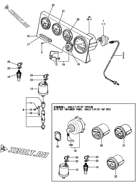
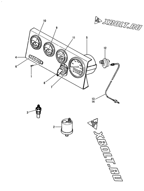
The diagram shows the assembly “Label” of the Yanmar 6HAL2C-EP engine.

Check sellers for 137900-91451 on pFind.pro

Where part 137900-91451 is used

Yanmar part 137900-91451 is used in 93 engine models. Assemblies: instrument panel, label, start/stop handle and 79 more.

Engine assemblyDiagram pos.QtyEngine modelsCatalogue notes
Label 5 14
Cylinder side/upper cover(mdo) 9 6
Exh.manifold cover(t/c fw.side) 24 12
Instrument panel 3 8
Fuel feed pump & driving device(clkw.) 19 2
Instrument panel 14 2
Label 9 2
Control valve 14 2
Fuel feed pump & driving device(cclkw.) 19 2
Cylinder side/upper cover(hfo) 9 6
NO.1 fuel strainer(32A/40A) 25 2
Start/stop handle 19 4
Start/stop handle 30 2
Governor(1200R.P.M.) 10 2
Air cooler(YPC190) 33 4
Instrument panel 2 2
Exh.manifold cover(t/c ofw.side) 25 12
Fuel strainer(NO.1) 18 2
Instrument board(6 gauge)(aux.engine) 22 2
Pressure gauge label(aux.engine) 8 14
Label 5 2
Instrument panel 28 12
Instrument panel 27 8
Instrument board(4 gauge)(aux.engine) 22 2
Cylinder side/upper cover(mdo)(auto decomp spec) 9 6
Label(radiator spec) 12 2
Label 12 10
Instrument panel 38 14
Instrument board(5 gauge/eng.side stop)(aux.engine) 22 2
Fuel feed pump 35 2
Instrument board(5 gauge/remoteness stop)(aux.engine) 23 2
Governor 64 1
  • Part superseded, not shown on the diagram
Instrument panel 10 4
Connecting collar 4 4
Air cyl. & link device(for a/c heater)(t/c fw.side) 42 6
Air cyl. & link device(for a/c heater)(t/c ofw.side) 34 6
Lub.oil pump(clkw.) 5 4
Lub.oil priming lines 37 2
Label(water tank spec) 13 10
Air cooler heater(YPC190-H75) 46 4
Lub. oil priming lines 37 2
Lub.oil pump(clkw.) 6 4
Instrument panel 1 2
Air cooler(YPC190) 49 4
(50A)instrument panel(6AL2-T/HT/DT) 1 2
Air cooler heater(YPC190-H75) 55 4
Instrument panel 7 6
Instrument 2 2
Instrument panel 62 6
Instrument panel (2) 1 2
Label 17 2
Instrument panel 38 10
Instrument panel 2 1 2
  • 4HAL(A01) = ELECTRIC STARTER 4HAL(A02) = AIR STARTER
Battery switch & terminal box 33 2
  • Not illustrated.
Instrument panel(mechanical) 5 4
Governor(mechanical type) 64 1
Govetnor case(governor motor/optional) 43 1
Pressure gauge label(main engine) 11 10
Instrument board(5 gauge)(main engine) 20 2
Instrument panel 3 16-1 4
  • Part superseded, not shown on the diagram
  • Interchangeability: quantity in the assembly changed
  • Applies from: date 1986.05
  • NEW TYPE ELECTRIC & MECHANICAL TYPE (T266A-5510D0)
Instrument panel 1 14
  • Part superseded, not shown on the diagram
  • Interchangeability: part is discontinued
Label 7 2
Instrument panel 3 16 2
  • PREVIOUS MECHANICAL TYPE (T266A-5510B0)
Air cooler 21 4
Instrument panel 1 2 2
Label 16 4
Thermometer 6 2
  • NOT ILLUSTRATED.
Instrument panel (3) 6 4
Label 16 4
  • OPTIONAL
Lub.oil pump(cclkw.) 5 4
Attachment part 8 2
Gauge spare parts 18 4
Governor case(governor motor) 42 1
  • Part superseded, not shown on the diagram
Label 5 10
Starting motor 11 2
  • Not illustrated.
Fuel strainer(N0.1) 25 2
Battery switch & terminal box 22 2
  • Not illustrated.
Instrument panel 62 4
Instrument panel (1) 2 2
Instrument panel 37 4
Instrument panel 11 4
Boost meter 7 2
Instrument panel (3) 24 4
Instrument panel 41 10
Tachometer 14 2
Exh.manifold cover(t/c ofw.side) 24 12
Instrument panel 2 2 4
Control valve(auto.starting) 24 2
Air cooler 17 8
Tachometer 12 2
Air cooler(YPC212) 48 4
Instrument panel 27 12
Instrument panel 27 10
Instrument panel 31A 16
Flywheel housing & clutch 15 4
Start/stop handle 18 4
Air cyl. & link device(for a/c heater)(t/c fw.side) 34 6
Instur.panel(electric starting) 19 6
Insturument panel(air starting) 6 6
Air cooler(YPC212) 32 4
Air cyl. & link device(for a/c heater)(t/c fw.side) 33 6
Instrument panel 3 1 2
  • Part superseded, not shown on the diagram
  • Interchangeability: part is discontinued
  • Applies from: date 1986.05
  • PREVIOUS ELECTRIC TYPE (T266A-5510A0)
Gauge(boost) 3 2
Air cooler 23 4
Instrument panel 31B 12
  • RADIATOR COOLING SPEC.
Instrument panel 27 2
  • NOT ILLUSTRATED.
Instrument panel 30 1
  • PARTS SHOW IN REMARK (1) ARE NOT ILLUSTRATED.
Instrument panel(4-press.eye) 3 8
Instrument panel for yeg(b) 21 2
Instrument panel for yeg(b) 55 8
Tachometer 11 2
Instrument panel(5-press.eye) 28 12
Load indicator 6 4
Instrument panel 20 2
Instrument panel 3 4
Instrument panel 7 4
Start/stop handle 15 4
Label 10 2
Label(water tank spec) 13 8
Instrument panel (1) 25 2
  • NOT ILLUSTRATED.
Meters & flexble shaft 2 2
Clutch 4 4
Instrument panel (3) 40 2
Instrument panel 101 2
Label 14 2
(51A)instrument panel(air starting) 5 4
Instrument panel(air starting) 5 4
Instrument panel & yap spec gauges 5 2
Governor(1500R.P.M.) 10 2
Fuel feed pump(kerosene spec.) 15 2
Instrument panel 44 2
Instrument panel 50 10
Speed contlor device 79 2
Governor driving device(psg) 82 2
Cyl.side cover & upper cover 13 6
Exh.manifold & connect.pipe,cover(t.fw.side) 46 12
Fo.feed pump & driving device 23 2
Lub.oil pump 6 4
Air cooler,blank.flange(square) & air cooler mtg.bracket 20 4
Exh.manifold & connect.pipe cover(t.ofw.side) 46 12
Fuel feed pump 17 2
Air cooler 37 4
  • NOT ILLUSTRATED. *1 ZINC
Label 1 12
Air control unit(optional) 1 2
  • FOR SPECIAL USER
Label 29 14
  • OPTIONAL.
Instrument panel(mechanical type) 5 4
  • 1500,1800R.P.M.
Instrument panel 30 1
  • NOT ILLUSTRATED.
Instrument panel 1A 14
  • FOR 6LAALG
Air cooler 22 6
Label 4 2
Label 22 2
Start/stop handle 25 2

Other parts of the “Label” assembly, Yanmar 6HAL2C-EP

Open the assembly diagram